|
|
|||||||||||
|
ATMEGA 128 Base- and MCU Board
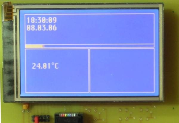
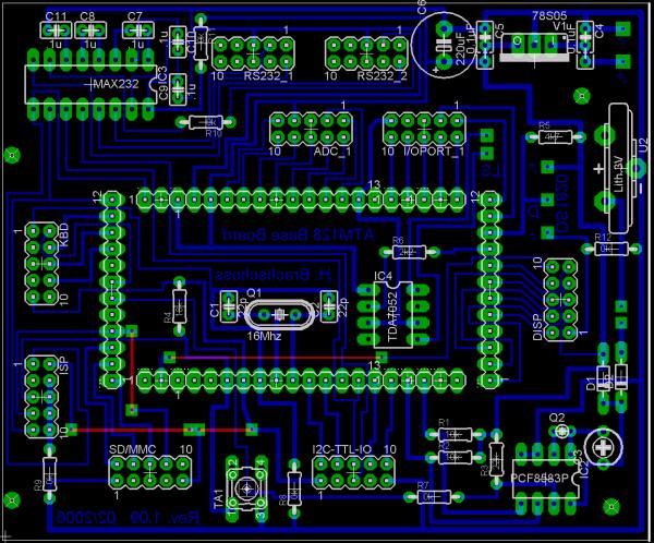
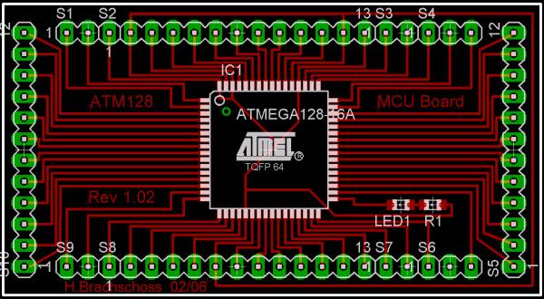
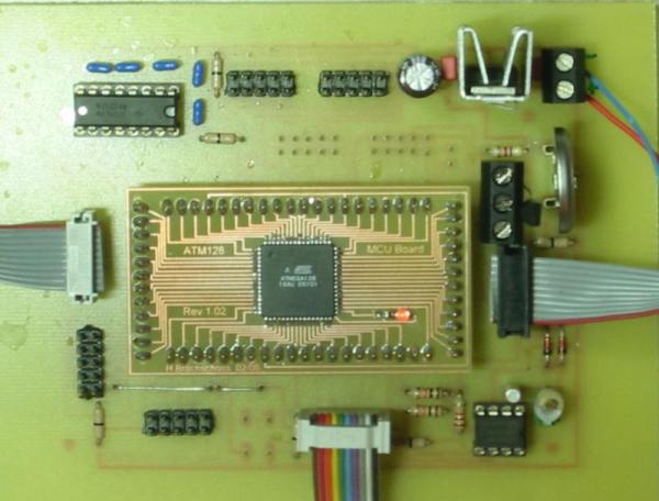
Development goal for this project was the need of more flash and ram for program development and datastorage. The project consists of two PCB’s. One is the MCU board which carries the ATMEGA 128 MCU and the second board is the peripheral board wich has a small Amplifier for sound output, two RS232 ports, several I/O ports, a battery backed up Hardware Clock, a Resetbutton, connectors for the I2C port and PWM outputs, ISP connector, Display and Keyboard ports etc. This board will replace my ATMEGA32 board from the pool heating project because it has more memory for temperature storage in a fixed time intervall over a 24 hour period. This temperature logfile will than be transfered to a PC for further analysis and temperature curve display.
Board’s are currently in hardware and software test condition for evaluation of all functions !
|
|
|
|